In the embedded system, the interface refers to the communication path or bus used to connect various integrated circuits with other peripheral devices. It is the connecting part and transfer station for information exchange between the microcontroller and the outside world.
Why do we need interfaces between the MCU and peripherals?
There are four major reasons listed as follows.
Introduction to Universal Interfaces
UART
Universal Asynchronous Receiver-Transmitter, commonly known as UART, is a full-duplex asynchronous transceiver, which is a part of computer hardware and transfers data between serial communication and parallel communication. As a chip converts parallel input into serial output, UART is usually integrated for connection with other communication interfaces.
A unique advantage of UART is that it can transfer data between devices using only two wires. In UART communication, two UART tranceivers directly communicate with each other. The UART transmitter converts the parallel data from the CPU into serial data and then transmit them to the receiving UART transceiver. The receiving UART transceiver hence converts the serial data back to parallel data for the receiving device. Data flow from TX pin of sending UART to RX pin of receiving UART is shown as in Figure 1:
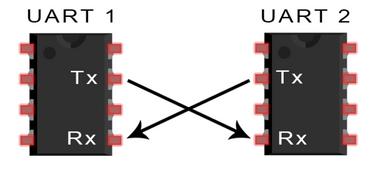
Figure 1. Diagram of UART Communication Connection
The UART communication protocol data frame is described as follows:

Figure 2. UART Data Frame
UART Communication Principle
Data transmission process: In an idle state, the circuit is at a high level. When receiving the data transmission command, pull down the level of the circuit for one data bit for time T, and then send the data from lower digits to higher digits. After the data transmission is completed, the parity bit and stop bit (stop bit is at a high level) are sent to wrap up the transmission of a data frame.
Data reception process: In an idle state, the circuit is at a high level. When an edge of voltage dropping is detected in the circuit, it suggests that data transmission has started. And the data is received from lower digits to higher digits according to the agreed baud rate. After that a parity bit is received and compared to see if the transmission is correct. If it is correct, the subsequent device is notified to prepare to receive the data or store it in the cache.
In embedded design, UART is used for communication between the MCU and auxiliary equipment, such as communication between car audio and external APs. Or the communication between the MCU and the PC including the monitoring debugger and other devices, such as EEPROM.
In BLE modules, UART transparent transmission has almost become a standard feature. The serial transparent transmission module is extremely convenient to use. Developers do not need to understand how the Bluetooth protocol stack is implemented. They can easily develop wireless products with the BLE Modules featuring UART transparent transmission.
Shenzhen RF-star Technology, as a wireless IoT module manufacturer, provides the UART serial BLE modules based on SoCs of TI CC2640 CC2642 CC264X, CC26X2, Silicon Labs EFR32BG22, Nordic nRF52832 nRF52810, and other domestic solutions. Supporting Bluetooth 4.2/5.0 in data transmission and reception, they are of industrial grade, compact in size, and boast of ultra-low power consumption. They facilitate users fast developing Bluetooth applications at extremely low cost.
SPI
SPI is the abbreviation of Serial Peripheral Interface. SPI interface is mainly used between EEPROM, FLASH, real-time clock, network controller, LCD display driver, AD converter, digital signal processor & decoder, and other devices.
As a high-speed full-duplex synchronous communication bus, SPI needs only four pins from a chip, thus saving pins of the IC and the space in the PCB layout as well.
Its four major pins are as follows:
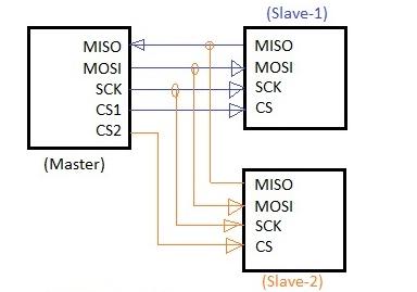
Figure 3. SPI Master-Slave Connection
In one SPI clock cycle, data transmission is to go through following operations:
This is achieved through shift registers. The master and the slave each have a shift register, and both are connected into a ring. At pace of the clock pulse, the data move out the master register and the slave register, in the sequence of highest digit first and lowest digit last, and then move in the slave register and the master register. When moving out is completed in the registers, the content exchange between them is completed. The data transmission is shown in Figure 4.
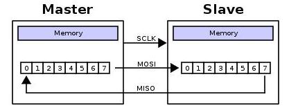
Figure 4. SPI Data Transmission
In SPI operation, the two most important settings are clock polarity (CPOL) and clock phase (CPHA). The clock polarity sets the voltage level when the clock is idle, and the clock phase sets the clock edge for reading data and sending data.
The master and slave send data at the same time, and both receive data at the same time. Therefore, in order to ensure correct communication between them, their SPI should have the same clock polarity and clock phase.
The following figures shows the communication process in four modes.
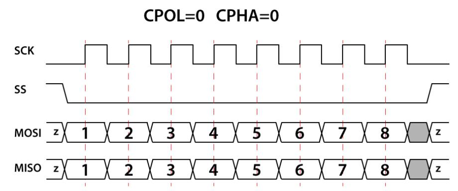
Figure 5. CPOL=0, CPHA=0
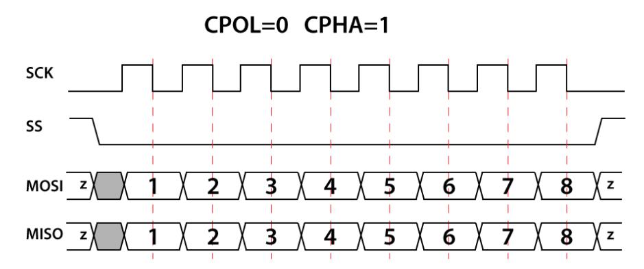
Figure 6. CPOL=0, CPHA=1
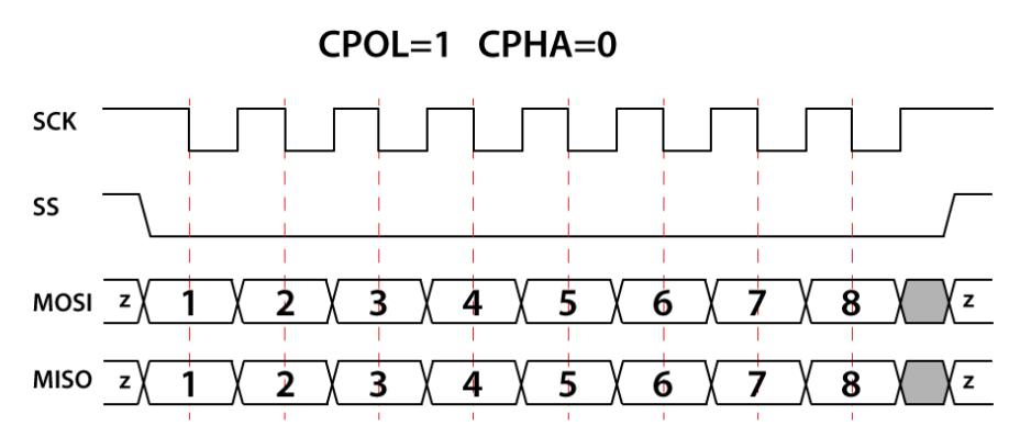
Figure 7. CPOL=1, CPHA=0
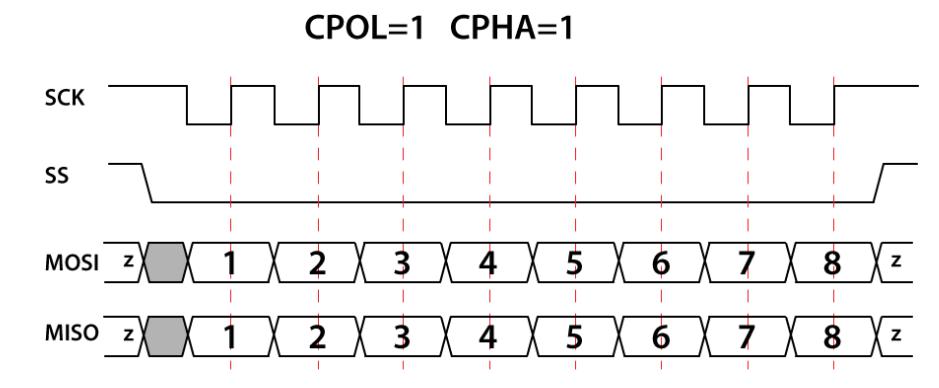
Figure 8. CPOL=1, CPHA=1
In the next chapters, we will discuss more on other peripheral interfaces, e.g. I2C, USB, ADC and CAN. Stay tuned!
About Us
Shenzhen RF-star Technology Co., Ltd. (RF-star) is a high-tech company focusing on radio frequency devices and has been certified by Texas Instruments as a third-party IDH of low-power RF products for more than a decade. RF-star provides IoT wireless modules and a full range of solutions, including BLE, Wi-Fi, Matter, Wi-SUN, Sub-1G, ZigBee, Thread, etc. For more information, kindly visit the company website https://www.rfstariot.com/or contact us at info@szrfstar.com.